G.fast is a new copper broadband technology that enables throughput of better than 1 Gb/s over a single twisted pair. The technology is based on a signal modulation scheme very similar to the DMT modulation used in VDSL2, with one notable exception, G.fast transceivers utilize time-division duplexing instead of the frequency-division duplexing used in VDSL2.
G.fast also borrows many other advances from VDSL2, including seamless rate adaption (SRA), bit swapping, retransmission, dying gasp, and vectoring. In addition, G.fast includes some new improvements such as the robust management channel (RMC), dynamic resource allocation (DRA), and fast rate adaption (FRA). Each of these features possesses a unique challenge in testing the transceiver’s functionality.
The key to successful deployment of any broadband technology is robust testing to ensure the core features of the deployed transceivers comply with the specifications; that it interoperate with systems from other manufacturers; and it doesn’t negatively impact the operation of other systems deployed in the broadband network. These testing requirements are no secret, as they have been followed for the many years of successful broadband deployments.
Making a Test Plan
Operators typically perform detailed lab tests, followed by trial deployments, and an eventual mass rollout. For the case of G.fast, the members of the Broadband Forum chose to pool many of the testing resources in the development of a detailed test plan, covering the functionality of G.fast systems and some basic performance and stability metrics. In this article, we’ll explore how some of these items are tested and/or how they affect the testing of other features.
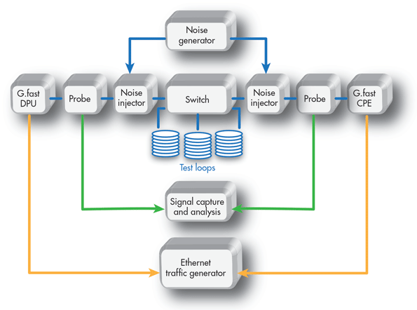
Before diving into the depths of the G.fast test cases, we’ll start with a brief explanation of the most common G.fast test setup. It covers the requirements for approximately 75% of the test cases in the Broadband Forum certification test plan, including the test cases for all of the features listed above. The key pieces of test and measurement equipment in the setup are the test loop and its associated switch, noise generator, digital signal analyzer (signal-capture system), and Ethernet traffic generator (Fig. 1).

1. The diagram illustrates the basic test setup for G.fast tests defined within ID-337. (Image by Nathan Miner)
Bit Swapping
Let’s start our exploration of G.fast testing by looking into the bit-swapping feature and its associated test case. Bit swapping allows a receiver to change the allocation of bits between subcarriers, due to a loss (lowering) of the signal to noise margin for the impacted carrier. In this event, the receiver requests the transmitter to alter the bit loading, moving the bits to other tones where there may be additional capacity.
To test the bit-swapping feature, the ID-337 test plan injects noise at each side of the test loop, where the noise level is elevated for a specific set of subcarriers. The G.fast systems are allowed to initialize the G.fast line in the presence of this noise. Once the line is stable, the noise level is lowered for the original set of subcarriers, while being increased for a different set of subcarriers. The end result is the transceivers must alter the bit loading over the sub carriers, without changing the total data rate for the connection.
