Also see: What is the TX_TCLK?
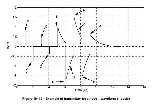
Subclause 40.6 of the IEEE 802.3-2005 Standard specifies that all 1000-T PMA devices must provide access to 4 transmitter test modes. These test modes are configured through PHY registers. Typical configurations are:
- Test Mode 1: Register 0: 0x0140, Register 9: 0x3f00
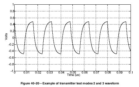
- Test Mode 2: Register 0: 0x0140, Register 9: 0x5f00
- Test Mode 3: Register 0: 0x0140, Register 9: 0x7f00
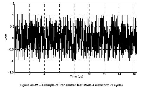
- Test Mode 4: Register 0: 0x0140, Register 9: 0x9f00
A sample configuration and waveform capture is shown below:
What is TX_TCLK?
Subclause 40.4.2.2 of the IEEE 802.3-2002 Standard specifies that the four transmitters, BI_DA, BI_DB, BI_DC, and BI_DD, shall be driven by the same 125MHz transmit clock, TX_TCLK. It is the clock that generates the 5 level Pulse Amplitude Modulated signal being driven onto the line. A sample configuration and waveform capture is shown below.
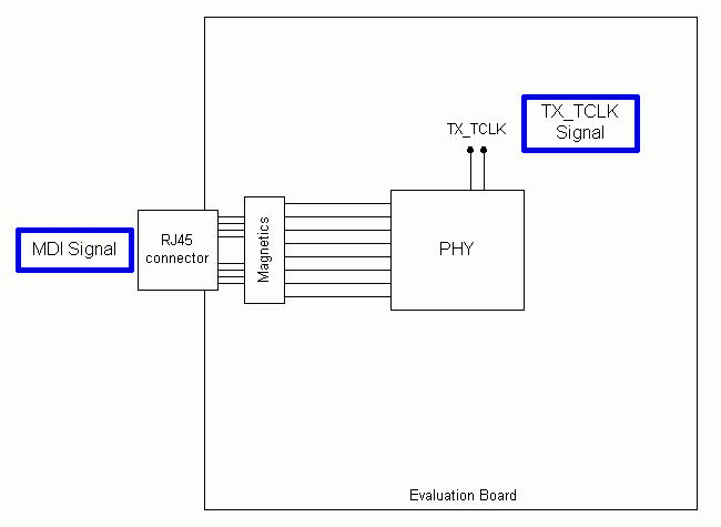
Sample TX_TCLK configuration
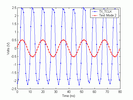
Sample TX_TCLK waveform, with Test Mode 2 waveform